Flow through Orifices.
In order to understand the formation of cavitation in flows through ports and orifices, a short look at the main equation governing orifice flow is helpful.
The flow through an orifice is controlled by the Bernoulli equation. Normally this is expressed as:
v2/2 + gz + p/ρ = const
Where v is the flow velocity,
g is the acceleration due to gravity,
z is the elevation of the chosen point,
p is the pressure at the chosen point,
and ρ is the fluid density.
For the horizontal flow the flow through the orifice, the elevation difference is zero,
the dynamic pressure q can be expressed as: q = ρv2/2
and the total pressure po is the sum of the static and dynamic pressures: po = p + q
For a given orifice area A, the flow rate Q can be expressed as:
Q= μA√(2Δp/ρ)
where Δp is the pressure difference across the orifice and μ is the flow coefficient of the orifice.
Orifice flow is usually determined by measuring the flow against a back pressure of atmospheric pressure. In diesel injection systems, the flow rate of injection nozzles is usually expressed as a flow (in ml/30sec or ml/min) of calibration fluid at a pressure difference of 100 bar across the nozzle into atmospheric pressure. For large engines where the orifice areas are large, lower pressures may be used.
Cavitation Theory
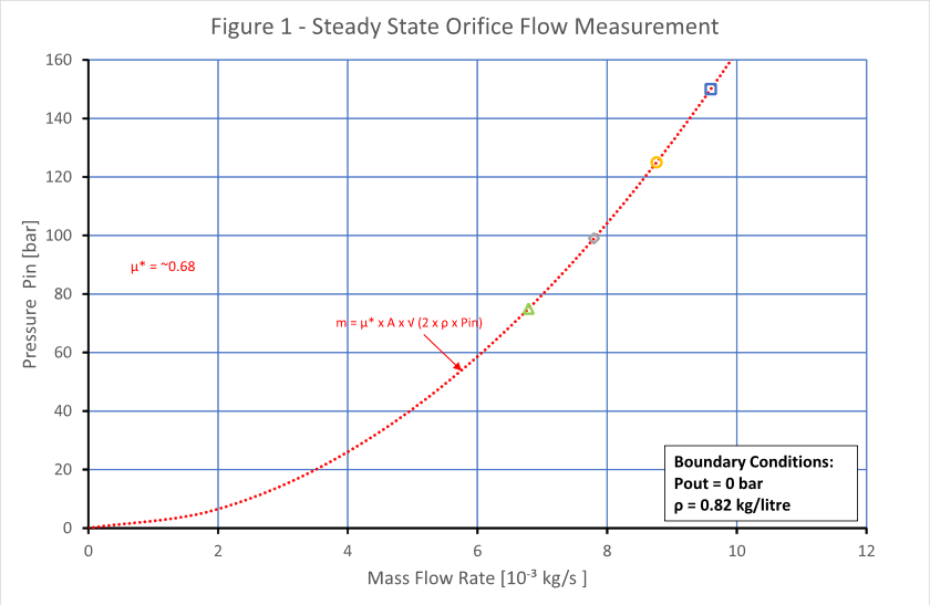
By way of illustration, the mass flow rate of a simple channel 0,3mm x 0,3mm and 0,7mm long was measured at different inlet pin pressures of 50, 75, 100, 125 and 150 bar and the back pressure pout is constant at atmospheric pressure – see Figure 1.
The flow rate follows the curve described by: m= μ* A√(2pin.ρ)
where μ*is the flow coefficient of the channel.
In this case the flow is proportional to the pressure difference pin -
However, if the measurement is repeated with constant inlet pressure and the back pressure is varied, then we see a different picture – Figure 2. In this case the measurements took place at inlet pressures of 50, 75, 100, 125 and 150 bar. In all cases the flow increases as the pressure difference increases until a point is reached at which the flow no longer increases despite an increasing pressure difference. The only way to increase the flow is to increase the inlet pressure. At each inlet pressure condition the same phenomena is repeated.
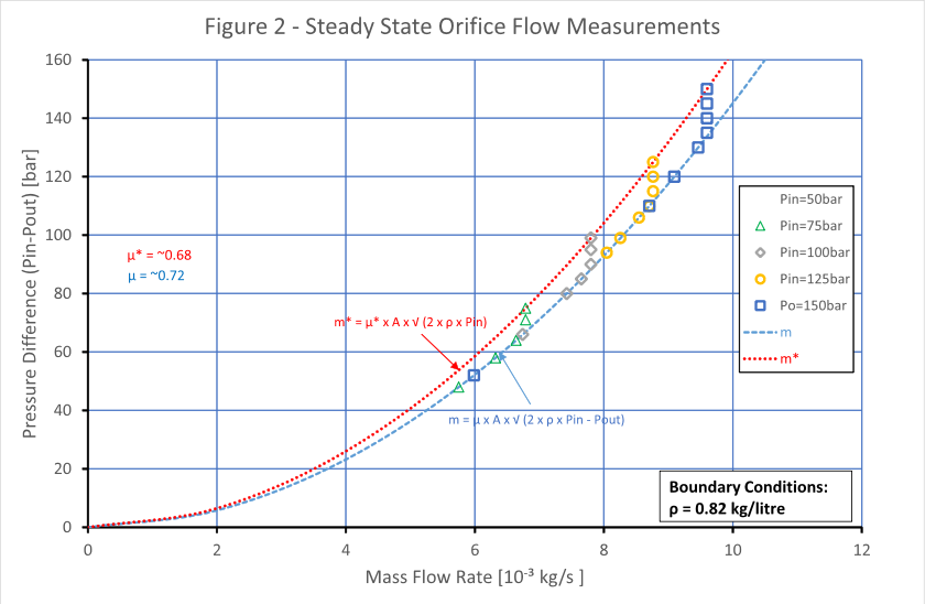
If one compares the two curves at the same mass flow rate, we see that:
m= μA√(2ρ(pin-
Simplifying the equations we get: (μ*/μ)2=((pin -
By plotting the mass flow rate against (pin -


It is interesting that in this representation, the flow rate at each pressure varies almost linearly with the pressure ratio (pin-
Topics of Interest